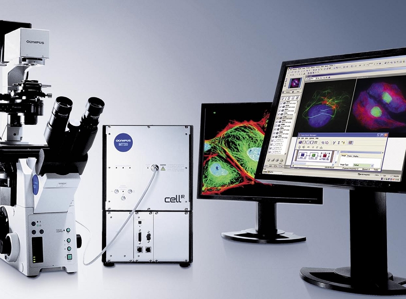
Live Cell station “Cell”
OLYMPUS Cell^R
The Next Generation Live Cell Imaging
INSIGHTS INTO THE SECRETS OF LIFE
Advanced applications in live cell imaging
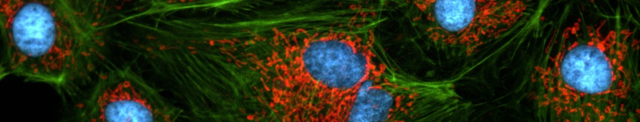
Microscopy in bioscience has progressed from the purely structural characterisation of fixed cells towards the investigation of processes in living cells with recent advances in fluorescence technology. Static morphological observation can now be complemented by the characterisation of the 3-D architecture of cellular structures and the real-time investigation of dynamic molecular processes in living cells. Newly developed fluorescence methods such as TIRF and FRET microscopy or GFP labelling are pushing the frontiers and widening the scope of bio-imaging.
Time-lapse Imaging
Dynamic processes such as cell growth, metabolic transport and signal transduction are monitored routinely nowadays. The duration of such processes may vary from the sub-second range to hours or even days. Consequently it may be necessary to take several images per second or just one image every couple of minutes.
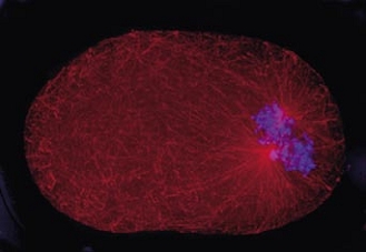
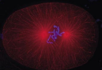
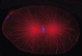
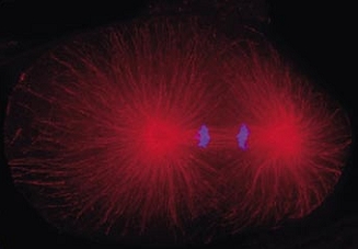
Cell division in the early C. elegans embryo, microtubules in red, DNA in blue.
Courtesy of K. Oegema, T.Hyman group, Max-Planck Institut, Dresden, Germany.
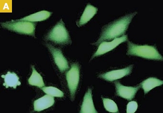
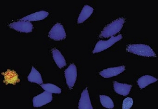
Multi-colour and GFP Imaging
The development of a growing list of specific fluorochromes covering the entire colour range enables the scientist to image and distinguish different sub-cellular structures simultaneously within one experiment through the use of multiple staining. If this is combined with time-lapse acquisition, the illumination unit of the microscope must be able to switch quickly between excitation wavelengths
Z-sectioning and Multi-dimensional Imaging
Microscopy is basically a two-dimensional observation technique while biological samples are three-dimensional. Therefore, in order to map the entire volume of the specimen, it can be imaged in layers by moving the focal plane in precise steps using a motorised Z-drive or a piezo-electric objective drive.
Ion Imaging / Ratio Imaging / Ca++ Imaging
The fluorescence behaviour of several dyes is dependent on the concentration of certain ions such as calcium (Fura-2) or on the pH value (BCECF). The detection,
quantification and analysis of changes in fluorescence intensity are thus an indirect means to study important physiological processes.
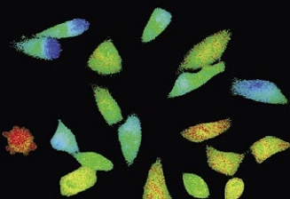
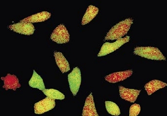
Time-lapse imaging:Fura2-labelled HeLa cells stimulated with APT.
Top : dual-excitation image; below; false-color ratio images revealing increasing calcium concentration.
FRET (Foerster Resonance Energy Transfer)
The measurement of fluorescence energy transfer from a fluorochrome molecule to an adjacent one can be used for the investigation of molecular interactions in cells. It requires the acquisition of images with different excitation and emission wavelengths and sophisticated correction algorithms.
TIRFM (Total Internal Reflection Fluorescence Microscopy)
Investigating surfaces without interference from background light can be carried out using Total Internal Reflection Fluorescence Microscopy. Laser light coupled together with the standard fluorescence excitation allows fast switching between TIRF and wide-field fluorescence applications and can even support simultaneous observation.
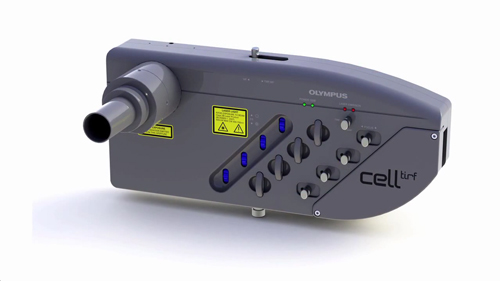
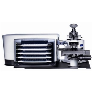
cell^tool TIRFM System
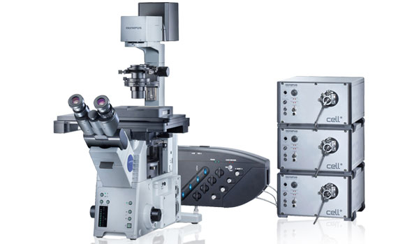
 cell^tool TIRFM is based on a modular multi-port illuminator for up to three lasers and a MT10 or MT20 widefield fluorescence light source. This extension of the cell^M and cell^R imaging stations allows for laser based high resolution cell surface and membrane studies with the possibility of simultaneous widefield observation. The control of the TIRFM illuminator is integrated into the ‘Experiment Manager’ of cell^M and cell^R software, so in addition to highest quality TIRF observation cell^tool TIRFM offers all the powerful options of the cell* imaging stations.
The cell^tool TIRFM is available as a complete turn-key solution or as an add-on for existing cell^M or cell^R imaging systems.
 Cell surface observation without out-of-focus blur
Fully integrated into cell^M and ^R imaging stations
Combination of up to three lasers plus a MT10/20 fluorescence illumination system
Optimised beam alignment on individual laser ports
Single molecule fluorescence detection with TIRFM
Commencing as a challenging problem in physics with the first detection of a single fluorescent molecule in condensed phase at temperatures of liquid helium single molecule fluorescence detection has diversified into a collection of methods applied in various scientific disciplines.
With the advent of ultra sensitive detectors and optical instrumentation and by combination with confocal and TIRFM techniques single molecule detection developed into a feasible approach in life science. Decisive for this adaptability is the possibility to detect single molecule fluorescence at room temperature in solution (e.g. FCS) or on surface membranes of even living cells (TIRFM).
The following experiment conducted on an inverse microscope using the Olympus UAPO150xO/TIRFM objective is an example of the many applications for TIRFM single molecule fluorescence detection:
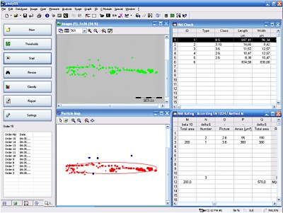
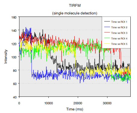
Single stranded RNA hybridised to a complementary biotinylated DNA, which was immobilised on a BSA-Biotin-Streptavidin coated cover glass. The RNA was mono-labelled with Cy3. Imaging of single molecules was confirmed by single step photo bleaching of the dye. Emission intensity plotted versus time decays immediately after bleaching a single dye molecule (ROIs 2-5), contrary to a group of fluorescent molecules whose emission would decrease in a multistep exponential manner (ROI 1).
Figure 1: Fluorescence intensity (colour coded. Circles mark five regions of interest (ROI). Each ROI (except of ROI 1) contains one single fluorescent molecule as verified by single step photobleaching: See movie with fluorescence intensity recorded over time (to download the film click on figure 1) and corresponding emission intensity curves plotted vs. time for the selected ROIs (Figure 2, bottom of the page).
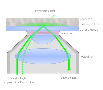
Total internal reflection (=TIR)
TIR is an optical phenomenon. If light is travelling through a medium with a high refractive index and strikes the interface of an optical medium with a lower refractive index at an angle greater than the critical angle, the incident light will undergo total internal reflection. Under these conditions some light still enters the low refractive index medium as an electromagnetic wave termed the evanescent wave. The intensity of this wave decays exponentially with penetration depth. The average z-expansion is less than 200 nm depending on the wavelength of light, the incident angle and the refractive index of the media. In TIRFM, fluorophores in the sample at a maximum distance of ~100 nm from the coverslip surface are selectively excited. This z resolution of 100 nm is one-fifth of an optical section obtained with a laser scanning confocal microscope. Therefore TIRFM is ideally suited for the observation of processes and structures on or close to the cell surface.
Total Internal Reflection Fluorescence Microscopy
Total internal reflection (=TIR) is an optical phenomenon. If light is travelling through a medium with a high refractive index and strikes the interface of an optical medium with a lower refractive index at an angle greater than the critical angle, the incident light will undergo total internal reflection. In biological investigations involving living specimen, these prerequisites are met if a laser beam travels through glass, for example a microscope slide (refractive index n = 1.52), towards an aqueous buffer solution or cell surface (n = 1.33 – 1.38). The beam is totally reflected at the interface between the glass and the medium or the cell surface respectively. But the reflected light generates an electromagnetic wave termed the evanescent wave which enters the low refractive index medium. The intensity of this wave decays exponentially with penetration depth along the z-axis. The penetration depth depends on the wavelength of light, the incident angle and the refractive index of the media. The thickness of the optical section that generates fluorescence under TIR can be adjusted by changing the incident angle and has a range between a few hundred and 50 nm at minimum. That is up to one-tenth of an optical section obtained with a confocal laser scanning microscope. Thus in TIRFM, fluorophores close to the coverslip surface can be selectively excited. As in confocal microscopy background fluorescence is nearly absent in TIRFM, because the fluorophore excitation is restricted to the focal plane of the objective. Therefore TIRFM gives high-contrast images of the cell surface with excellent signal-to-background ratio and is ideally suited for the observation of processes and structures on the cell surface and within or close to the plasma membrane.
In contrast, widefield fluorescence microscopy provides limited spatial resolution in z-direction because background fluorescence from outside the focal plane often impedes the detection of small or weakly fluorescent structures.
TIRFM does not require the rather expensive scanning microscope technique because it generates widefield illumination at the specimen surface. It can be performed relatively cost-efficient with inverted fluorescence microscopes equipped with a special episcopic fluorescence illuminator, special high NA objectives and a laser.
Confocal microscopy has the clear advantage in not being restricted to the optical section directly adjacent to the coverslip/specimen interface. However optical sections obtained by TIRFM can be up to one order of magnitude thinner than by confocal microscopy. Further-more, being a widefield technique, TIRFM comprises the considerable advantages of a higher acquisition speed as compared to scanning microscopy.
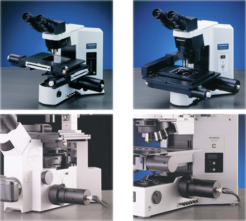
The TIRF Microscope
TIRFM is a widefield microscopy technique and consequently modified fluorescence microscope set-ups are used. Lasers are commonly employed as illumination sources because the light is coherent, polarised, intense and well collimated. If a special dual port epi-fluorescence condenser is used the change from widefield illumination with a standard arc lamp to the TIRF laser is rapid and straightforward and does not interfere with the beam alignment.
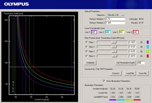
For TIRFM with inverted microscopes, the incident beam is focused off-axis at the objective back focal plane such that it passes the very periphery of the pupil of a highly refractive objective. The objective’s numerical aperture must be at least 1.38 to exceed the refractive index of a living cell. Thus the incident beam emerges from the front lens into the immersion oil in such a way that it reaches the glass/cell interface in a critical angle and undergoes total internal reflection. The off-axis position of the laser beam determines the incident angle and the depth of the evanescent field accordingly. The further off-centre the alignment is, the larger is the angle and the shallower is the evanescent wave.
Olympus offers a range of special TIRF objectives with very high numerical apertures (NA). There are three objectives available with a NA of 1.45 that can be used with conventional immersion oil and cover slips. With the PLAPON60xO/TIRFM-SP, the PLAPO100XO/TIRFM-SP or the new UAPO150xO/TIRFM-SP a penetration depth of the exciting wave around 100 nm is reached. The UAPO150xO/TIRFM is especially designed for single-molecule detection in TIRFM. The APO100XOHR features an unsurpassed NA of 1.65. To match the extreme high NA special high-refraction cover slips and special immersion liquid (diiodomethane) are required. Therefore the objective offers a unique short penetration depth of about 50 nm and high flexibility regarding the marginal angle available for TIR. The 60x and the 150x objec-tives have a temperature correction collar. Common plan apochromatic objectives like 100x with NA = 1.40 can also be employed for TIRFM, but they are less convenient due to the small angle that is available for the total internal reflection.
Applications
The visualisation of molecular interactions on surfaces is of fundamental interest in cell and molecular biology because many molecular transport and signal transduction processes are transmembrane incidents. Examples are binding and triggering of cells by hormones, neurotransmitters and antigens, cell adhesion to surfaces, electron transport in the membrane, cytoskeletal and membrane dynamics, cellular secretion events and vesicular fusion events with membranes. TIRFM is the perfect tool for visualisation of these processes. The extraordinary small depth of field of TIRFM assures that only surface-bound fluorophores are detected. Fluorophores in the surrounding medium remain invisible though they might be in rapid exchange and be present in large excess. This is different from normal widefield illumination where they would create overpowering background fluorescence.
During many experiments it might be desirable to switch rapidly between TIR illumination to observe the surface and standard epi-illumination to investigate the deeper layers of the specimen as well. For example, a transient process may involve simultaneous but not identi-cal processes in the membrane and the cytoplasm. The Olympus BioSystems dualport illuminator for combined TIR and widefield illumination allows the fast and synchronised alternation of the two techniques. The techniques of TIRFM, DIC and other microscopy techniques as FRET, FRAP and FLIM can also be combined.
Cell Software 소개
준비중입니다.
Cell Hardware 소개
Cell Hardware features
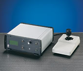
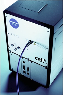
1. MT20 광원 장치
Cell 시스템에서 가장 중요한 장치 중 하나인 광원 장치는 MT20 광원 시스템을 사용합니다.
MT20 광원 장치는 두 가지 타입의 램프 (Xeneon 혹은 Xe/Hg)을 사용할 수 있으며 전원 장치가 내장되어 뛰어난 광량의 안정화를 이루었습니다.
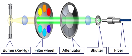
또한 내장된 8개의 필터 장착 휠은 고속의 회전으로 즉각적인 필터 변경을 가능케 하며 14단계의 광량 감쇄기 휠 뿐만 아니라 1ms의 고속 셔터도 지원합니다.
1. 병렬 처리
– 필터 교체
– 셔터 개폐
– 광량 조절
시편의 Bleaching 감소를 가능하게 합니다.
2. 광원 소스의 안정성 증대
정량 분석에 필수적인 조건
3. 사용자 친화적
도구가 필요하지 않은 필터 장착
[ MT20 광원 시스템의 광학 설계 ]
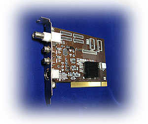
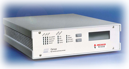
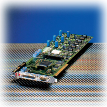
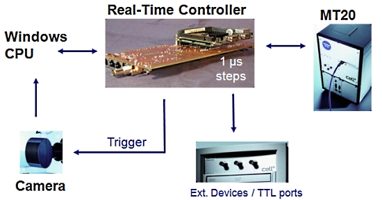
2. 실시간 제어기 (Real-Time Controller)
Cell 시스템에서 또 하나의 매우 중요한 장치로 이미징 워크스테이션 내의 실시간 제어기 (real time controller)보드가 있습니다.
이 실시간 제어기가 광원 장치, 카메라 및 현미경의 제어를 실시간으로 하드웨어적인 처리를 제어 함으로써 시편의 Bleaching을 극소화 할 수 있습니다.
또한 Time point 기반의 실험에서 1us 단위의 매우 정확한 Time point를 보증할 수 있게 하여 분석 결과의 신뢰성을 높여 줍니다.
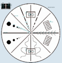
[ 실시간 제어기의 이점 ]
A. 필터 휠 (Filter wheel)을 사용한 일반적인 이미징 시스템
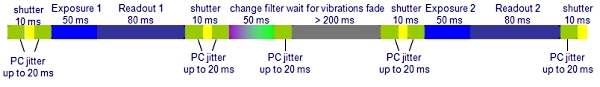
하나의 이미지 쌍을 획득하는데 650ms 이상의 시간이 걸림
B. Cell^R 병렬 처리 시스템

Cell^R 실시간 처리기 사용시 최소 2배 이상 빠름
위의 처리 순서 비교 이미지를 보면 셔터 개폐 시간 10ms, 카메라 노출 시간 50ms, 카메라 Readout (데이터 전송) 시간 80ms, 필터 교체 시간 50ms 기준으로 두 시스템간의 차이를 비교 한 것입니다.
일반적인 순차 처리 방식의 시스템의 경우 PC에서의 지연 시간 및 필터 교체등에 의한 진동의 영향을 받게 됩니다.
Cell 시스템은 실시간 처리기를 사용함으로써 일반적인 순차적인 제어가 아닌 병렬적인 동시 제어가Hardware적으로 가능함을 알 수 있습니다.
이는 더 장시간의 더 많은 이미지를 Bleaching이나 Cell Dead가 없이 정량적 분석이 가능함을 나타내며 동일 조건시에 더 많은 노출 시간을 확보할 수 있음으로 카메라의 영상 품질의 향상 역시 기대할 수 있습니다.
위 이미지에서 샘플에 형광 Excitation이 노출 되는 시간을 비교하면 A의 경우 170msec, B의 경우 50msec 로 1/3 이하의 노출 만으로 동일한 조건의 이미지를 획득할 수 있게 됩니다.